Case studies/APIA — Infrastructure rebuild
Public sector · Compute, storage & virtualisation · Romania
APIA — Infrastructure Rebuild
Storage that had fallen out of support, carrying data that could not wait. 34 servers, two all-flash arrays and a redundant network across two sites — with the live data migrated off the failing estate underneath running workloads.

01The challenge
Replacing the floor while people are standing on it
APIA’s central IT node was running on storage that was ageing out of vendor coverage. A considerable part of the existing capacity was no longer under warranty or support, and the workloads on it were the agency’s own — they could not simply be paused.
The task was to install a new platform across two sites, move the live data onto it with as little interruption as possible, and leave behind something that extends by adding hardware rather than by being replaced again.
02Scale
What was installed,
across two data centres.
Five 42U cabinets, thirty-four dual-socket servers, two all-flash arrays holding sixty-two enterprise SSDs between them, four data-centre switches, two out-of-band management switches and a three-phase parallel-redundant UPS — delivered, racked, cabled and configured across a headquarters site and a secondary data centre.
03What was delivered
Seven layers, one delivery
Compute, storage, the data services on top of it, network, virtualisation and power were supplied and configured as one integrated solution — every licence included, every system at its current release on the day it went in.
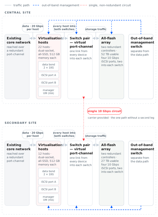
Twenty-two hosts at the central site and twelve at the secondary, each with two 24-core processors, 512 GB of memory and five enterprise SSDs. Racked in pairs for airflow, across five 42U cabinets with dual power distribution.
One all-flash array per site — 40 SSDs giving 52 TB usable at the central site, 22 SSDs giving 27 TB at the secondary, both in RAID 5. Each array carries two hot-swap controllers with 128 GB of cache apiece, battery-backed so cache is flushed to flash on power loss, and every software feature licensed and enabled.
Inline compression and deduplication for both block and file volumes, thin provisioning, automatic tiering that moves hot blocks onto the fastest media, snapshots and thin clones for production copies, and journaled replication that allows recovery to any point in time, grouped per application so interdependent systems come back consistently.
Fibre-channel and iSCSI for block access alongside SMB, NFS, FTP and SFTP for file — so the array serves both the virtualisation platform and file workloads without a second system.
Two data-centre switches per site with 10/25 Gbps access ports and 100 Gbps uplinks, configured as a virtual port-channel pair. Every device lands one port in each switch: a single switch can fail without dropping a path, and while both are up their capacity adds together — 20 Gbps of data per host. Storage traffic is isolated on its own VLAN that exists only locally.
An enterprise Linux hypervisor on every server, all licensed for virtual datacentre use. Each site is managed by its own manager, which itself runs as a highly-available virtual machine on the cluster — if its host fails it restarts elsewhere, so the management plane survives the loss of a node.
A parallel-redundant 40 kVA three-phase UPS at the central site, with two power distribution units per cabinet, each fed from an independent UPS or generator source, so no equipment depends on a single supply path.
04Architecture
Every device dual-homed
The diagram shows the reference architecture model — not the actual internal implementation. The principle is visible in it: at each site, every device lands one port in each of two switches, storage is reached over four independent paths, and the management network is entirely separate from the data path.
05Migration
Moving data off a failing array
The migration was the difficult part of this project, not the installation.
06Outcome
What the agency ended up with
Data off the risk
The workloads that were sitting on unsupported, out-of-warranty storage now run on two fully-licensed all-flash arrays with redundant controllers and battery-backed cache.
A path that survives failure
Dual controllers, dual switches, dual power feeds, bonded host interfaces and dual storage ports — every layer of the delivered platform has a second leg.
Performance where it is needed
All-flash media with automatic tiering, inline compression and deduplication, and 20 Gbps of data per host.
An estate that extends
Additional drives, additional hosts and additional shelves are all in-place operations, so the next growth step is not another rebuild.
07Confidentiality note
We do not disclose site addressing, host naming, credentials, rack layouts or the actual internal technology architecture of the project.
The diagram and figures on this page describe the reference architecture model and the publicly communicable scale of the engagement.