Case studies/Frontend Web Applications Platform
Public sector·Container platform, private cloud & storage·Romania
Frontend Web Applications Platform
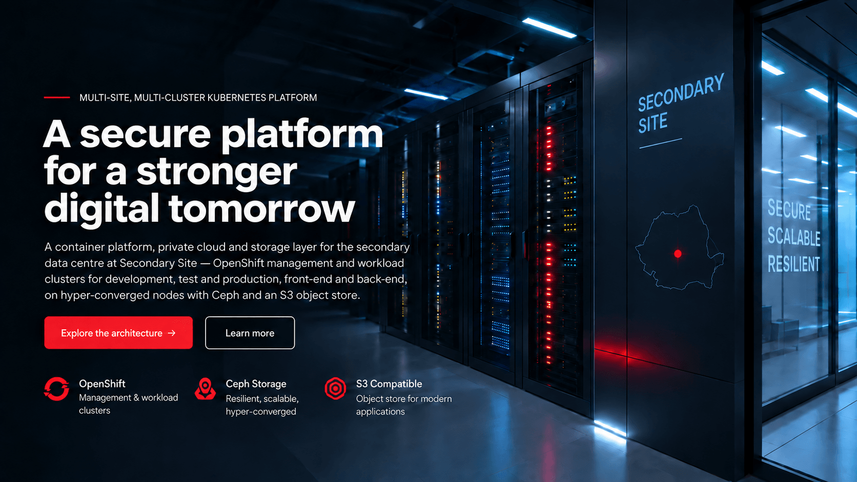
A complete container platform, private cloud and storage layer for the secondary data centre — built as a peer to the primary site, with separate clusters for development, test and production, each split front-end and back-end.
01The challenge
A second site that can carry the same platform
The estate’s container platform, private cloud and storage ran from a single primary data centre. Services used by citizens and businesses could not be left depending on one building, one power feed, one network path.
The mandate was to stand up the same platform in a second data centre — at the secondary data centre — capable of operating on its own or alongside the first, without changing the applications running on top of it.
02Scale
Sized for the platform,
built to lose components.
Per site: a four-node management cluster on bare metal, ten hyper-converged nodes running compute and storage together, a five-node object platform, and two redundant switch pairs dual-homed into the existing core.
03The platform
Eight layers, one platform
The container platform is the centre of this build. Everything else — the private cloud, the storage, the fabric — exists to serve the workloads running on it.
Three combined control-plane and worker nodes plus one dedicated worker. The control-plane nodes carry etcd, the API server, the scheduler, the controller manager and the cluster version operator; the fourth node runs workloads only. Three control-plane nodes give etcd its quorum, so the cluster survives losing one.
The management cluster hosts what the rest of the estate depends on: advanced cluster management across the fleet, an image registry, an automation platform, machine management, lifecycle management and a directory service — plus the software-defined networking, DNS and routing that the clusters themselves run on.
Application workloads run on their own clusters, separated by environment rather than by namespace alone, and each environment is split into a front-end cluster and a back-end cluster. Promotion between environments is a deliberate act; a back-end change cannot take a front-end with it.
The private-cloud control plane — identity, compute API and scheduler, networking API, images, orchestration, placement, dashboard, block and shared-file services, telemetry — runs as distributed pods on the management cluster rather than on its own controllers, so it inherits the same high availability and the same lifecycle.
Ten mixed nodes per site run compute and storage together: hypervisor instances, virtual networking agents and volume services alongside the distributed storage daemons. Capacity for virtual machines, network functions and persistent volumes grows by adding nodes.
Block, file and object storage on the same nodes that run the workloads, presented to the container platform through its storage operator — so a pod asking for a persistent volume and a virtual machine asking for a disk are served by the same pool, replicated across nodes.
A separate five-node object platform with a standard S3 interface holds long-term log retention and backup, with data replicated across all nodes so losing one node does not lose information. It is consumed primarily by the container platform for archival.
Two switch pairs per site — one for 10/25G server connectivity, one for 40/100G — each configured as a virtual port-channel pair and dual-homed into the existing core network at 40 Gbps.
04Architecture
Management cluster on top, storage underneath
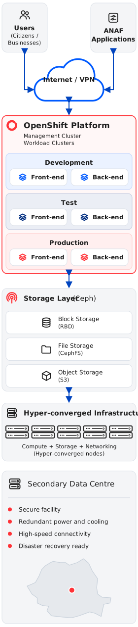
The diagram shows the reference architecture model — not the actual internal implementation. Each site runs its own management cluster, which provisions and governs the workload clusters below it; the private cloud and the storage layer sit underneath, and the two sites share one operating model with replication between them.
05Cluster model
Why the clusters are separate
Separation is the cheapest safety mechanism a platform has. Environments do not share a cluster, and inside each environment the front-end and back-end tiers do not either.
06Storage
One storage layer, every access mode
Hyper-convergence means the nodes that run the workloads also hold the data. That removes a whole tier of hardware — and makes capacity a single planning exercise rather than two.
07Resilience
What survives a failure
08Confidentiality note
We do not disclose addressing, host naming, rack layouts or the actual internal technology architecture of the project.
The diagram and figures on this page describe the reference architecture model and the publicly communicable scale of the engagement.